TEA5767 FM Radio
Darren Prong
N00678964
GitHub: https://github.com/DarrenProng/Hardware-Production
Week 15 (Dec.11th)
Week 14 (Dec.4th)
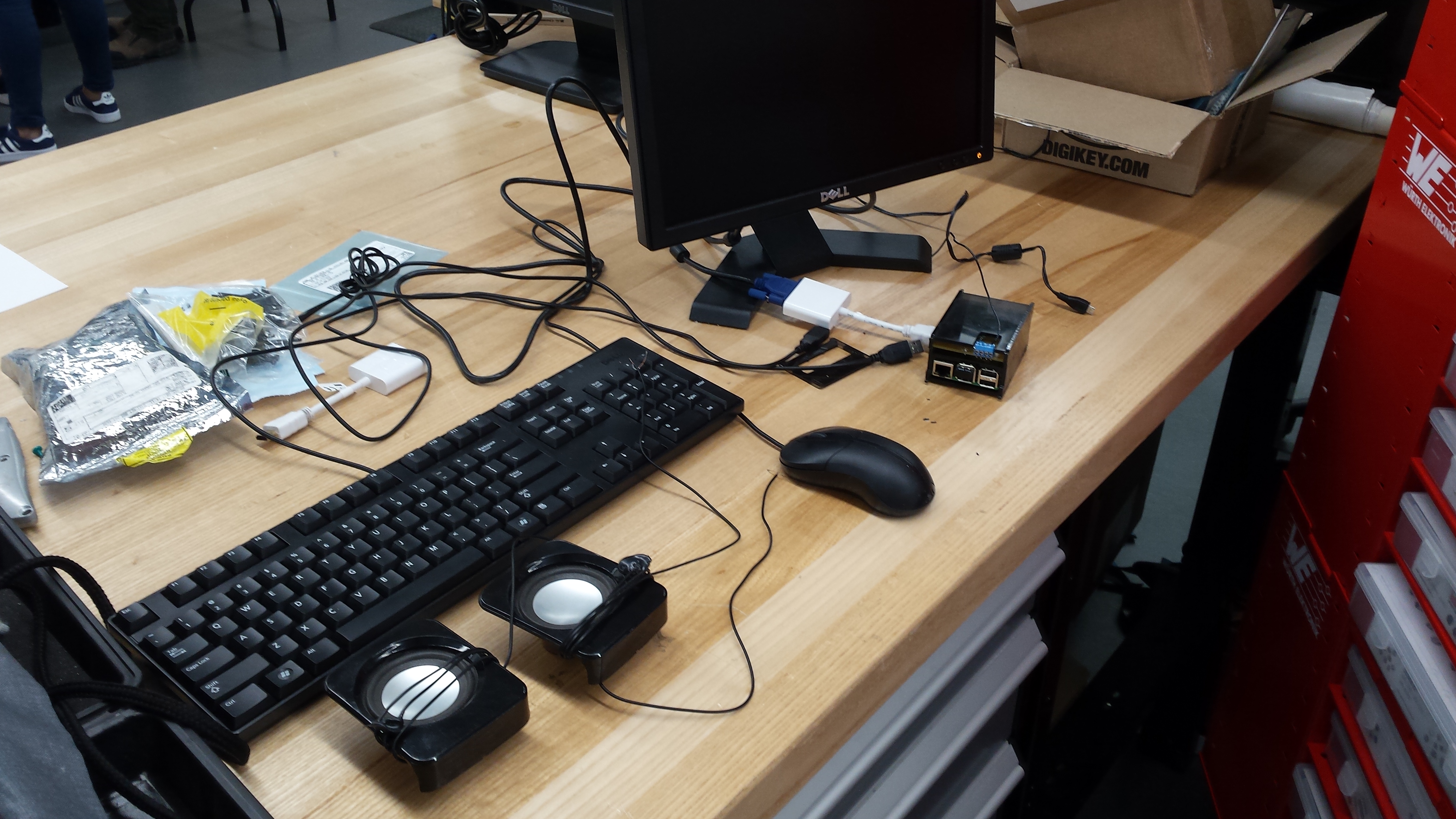
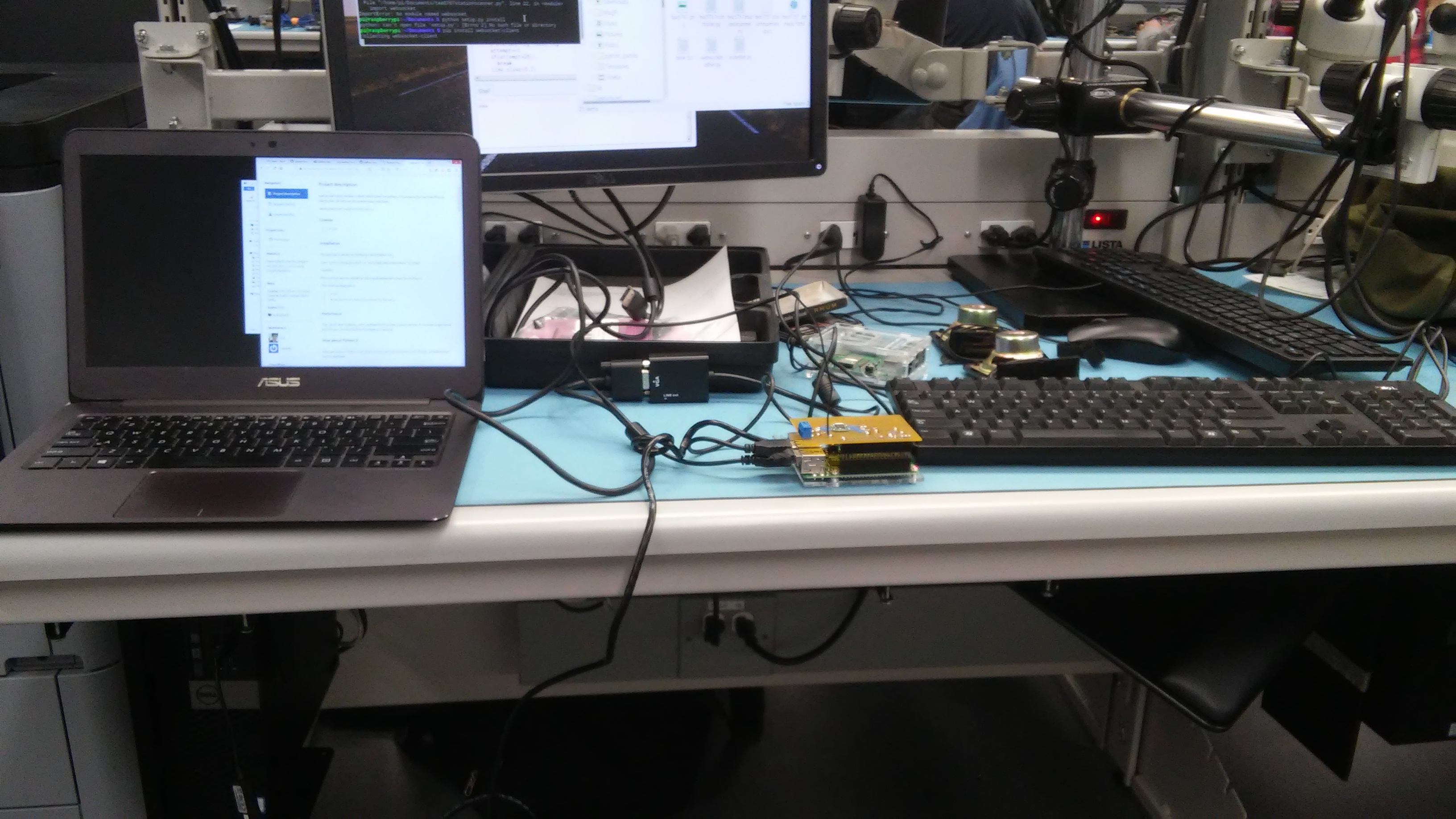
My setup for testing;
- a monitor,
- keyboard and mouse combo,
- wireless bluetooth dongle,
- Raspberry Pi power adapter from CanaKit,
- Raspberry Pi itself,
- two speakers around 4ohms,
- acryllic enclosure,
- soldered TEA5767 PCB device,
- LCM386 amplifier set up on a,
- Breadboard with,
- Associated capacitors and resistors and wires,
- 12v DC power
Had to finish up this week as my final presentation was due at the end of class. I pushed through some other assignments I had to complete, so I could then rush into the prototype lab for help in completing the radio. Heres a video of how the final prototype functions.
It works pretty good, with little distorion or static. Any range of frequencies are available; from 88.9 to 107.9. Although I havent tested all frequencies as our lab is mainly enclosed in concrete, limiting outside frequencies. getting inside. However, what you hear tuned in is our local college radio station, 96.9.
The Pi in action
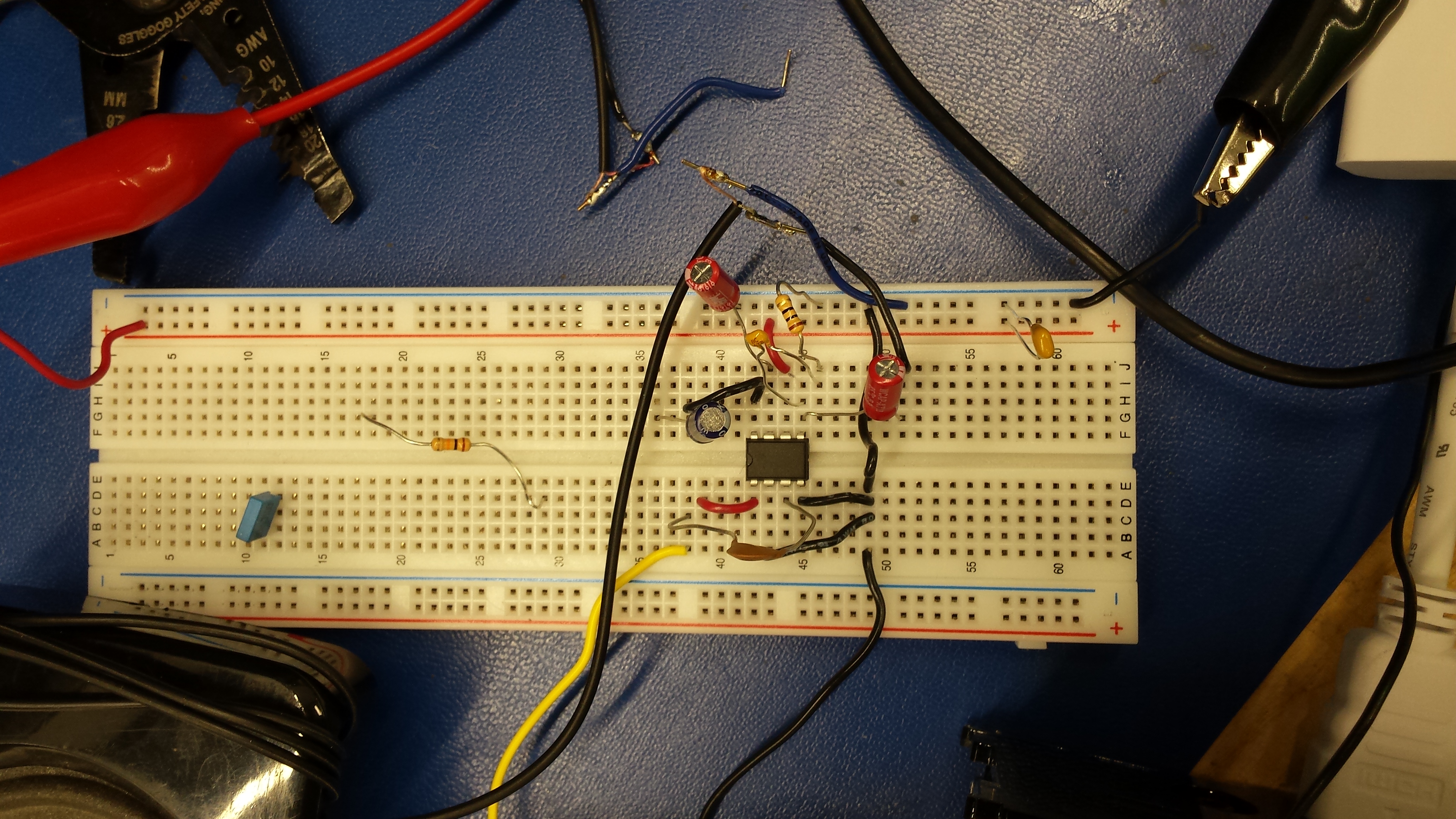
LCM386 Amplifier
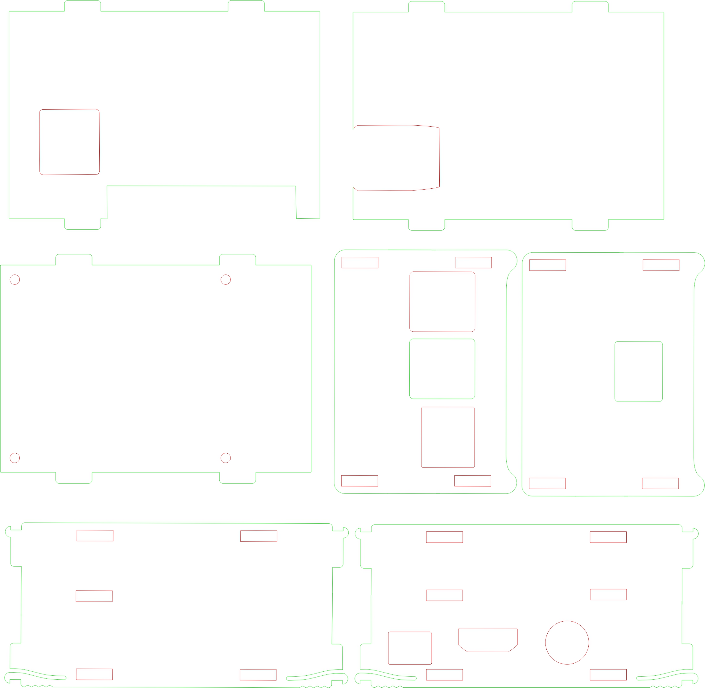
The enclosure itself I had to finish over the weekend as it still needed tweaking so the device and Pi could both fit in comfortably. Here's my final design file:
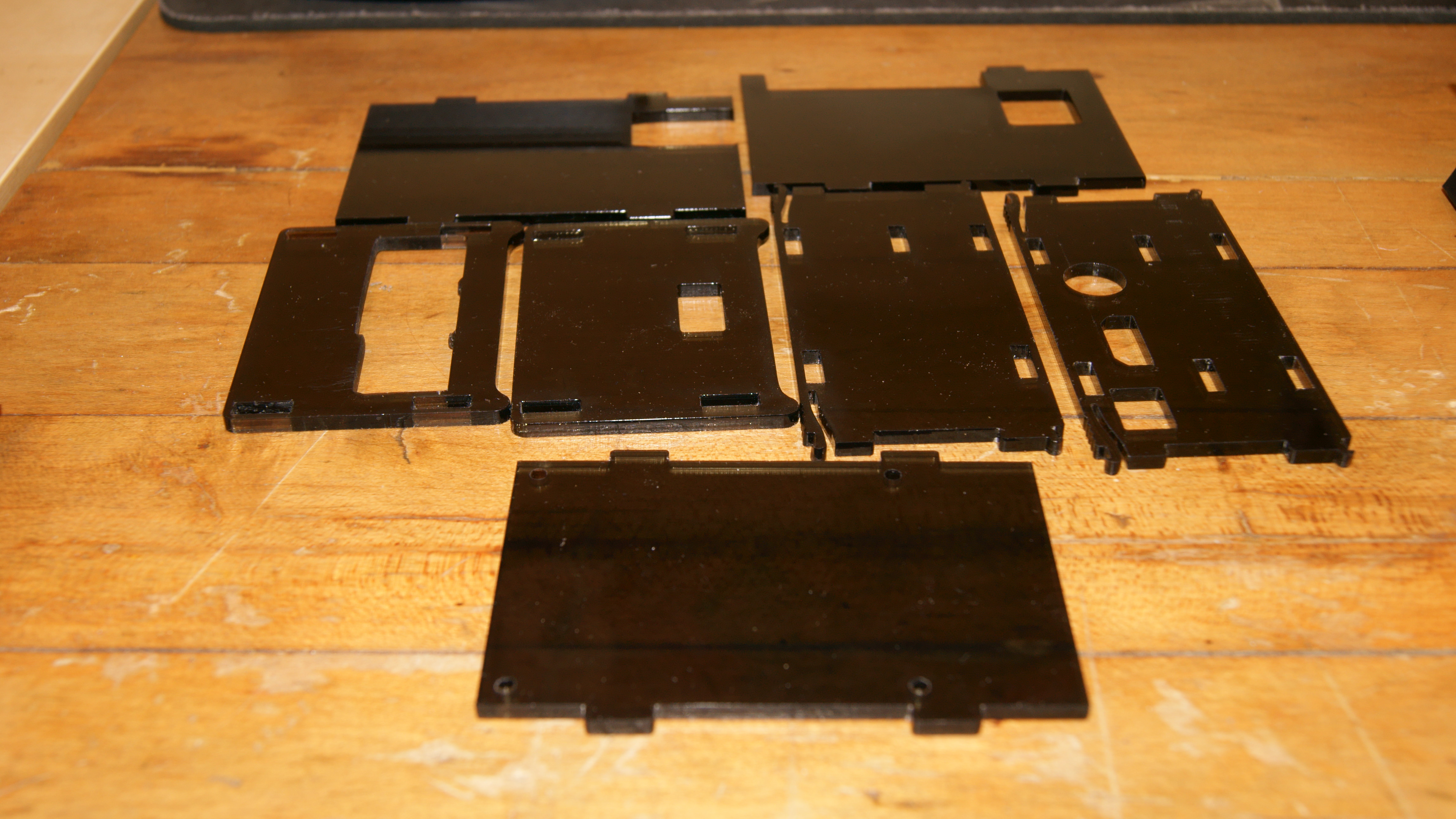
As well as, the printed product:
Week 13 (Nov.27th)
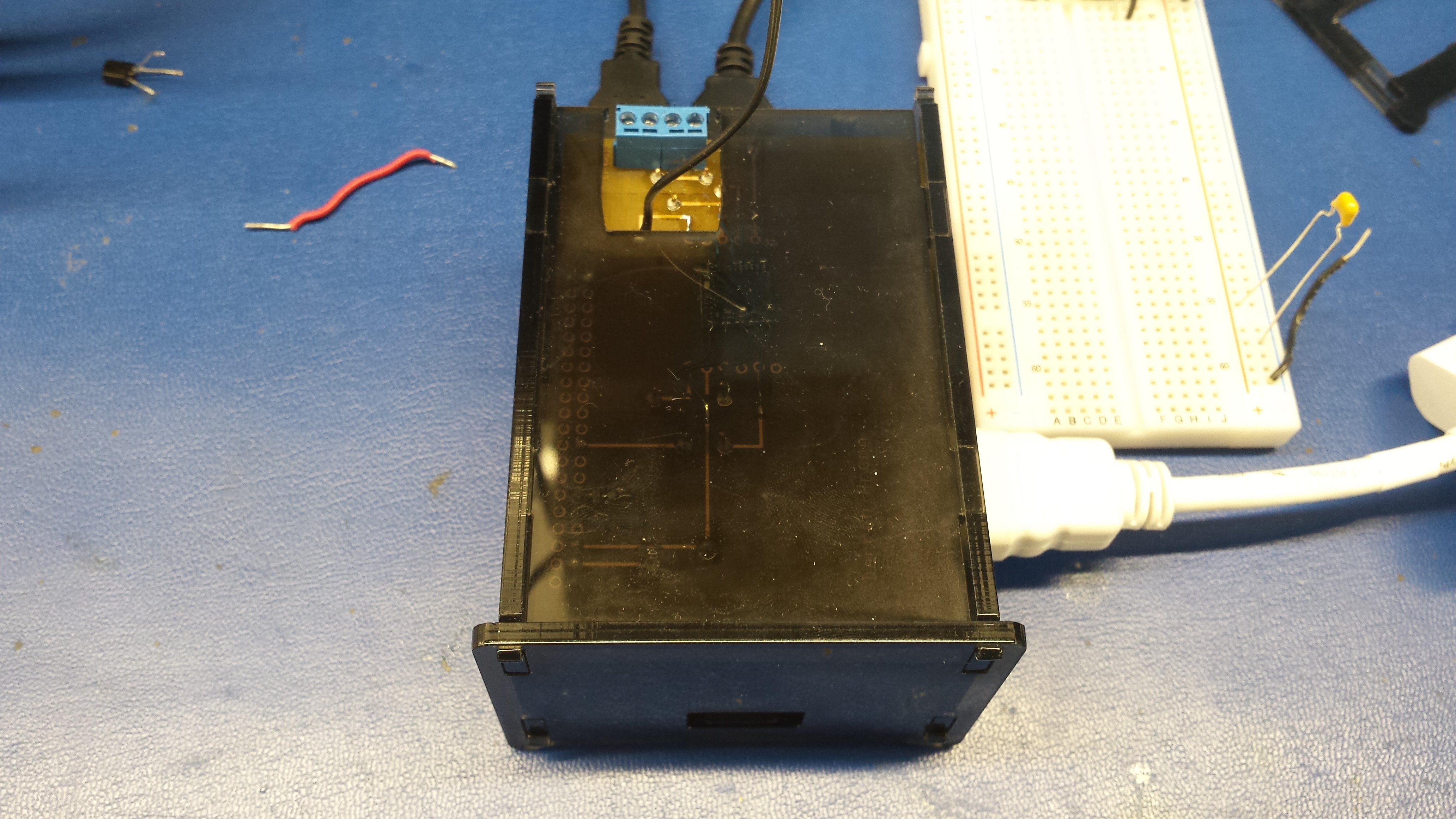
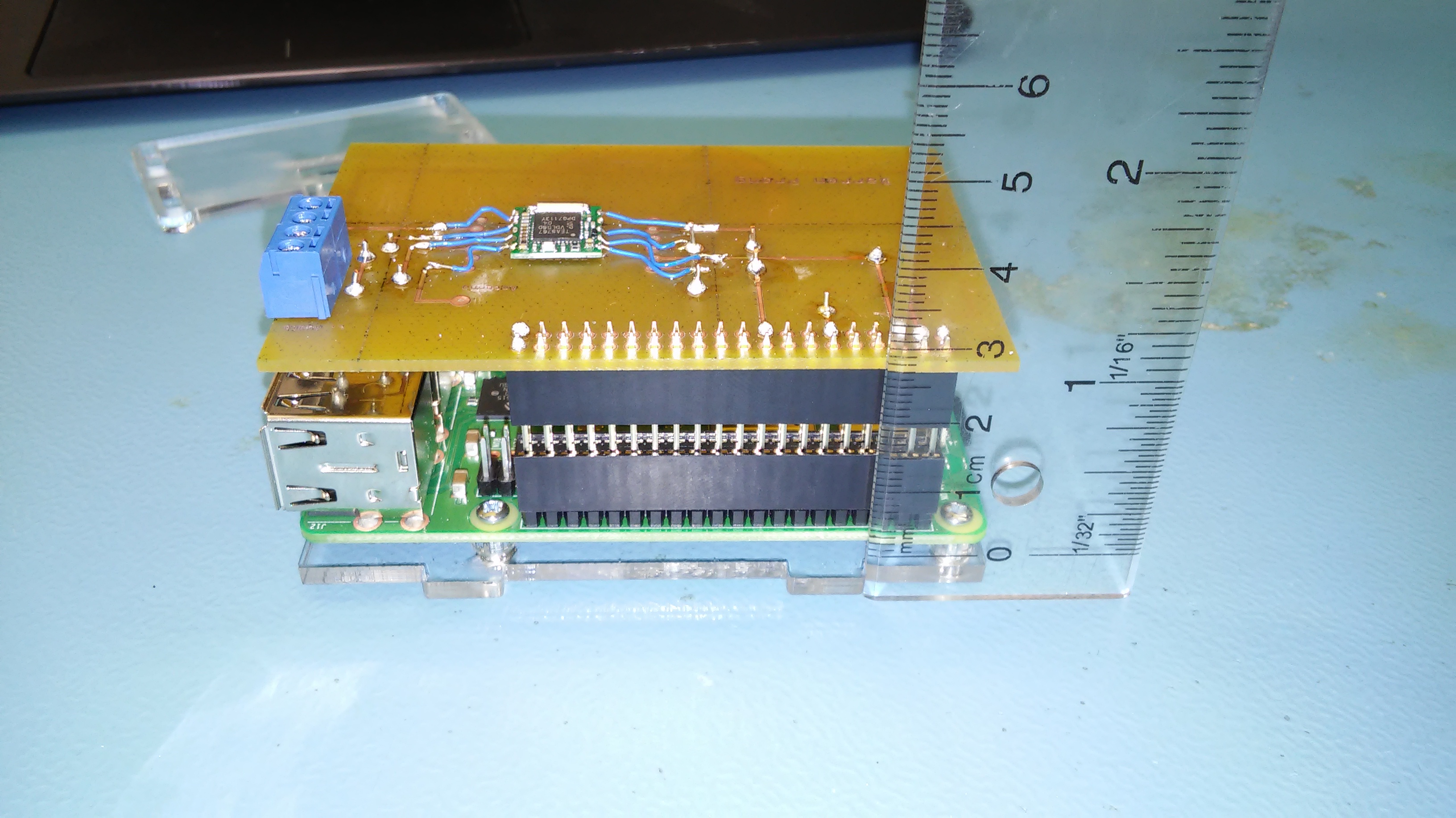
This week I designed and printed a enclosure meant to house my PCB/device which is attached to the PI via a 40pin stackable header. It was looking promising until I actually placed the PCB inside. Heres a pic:
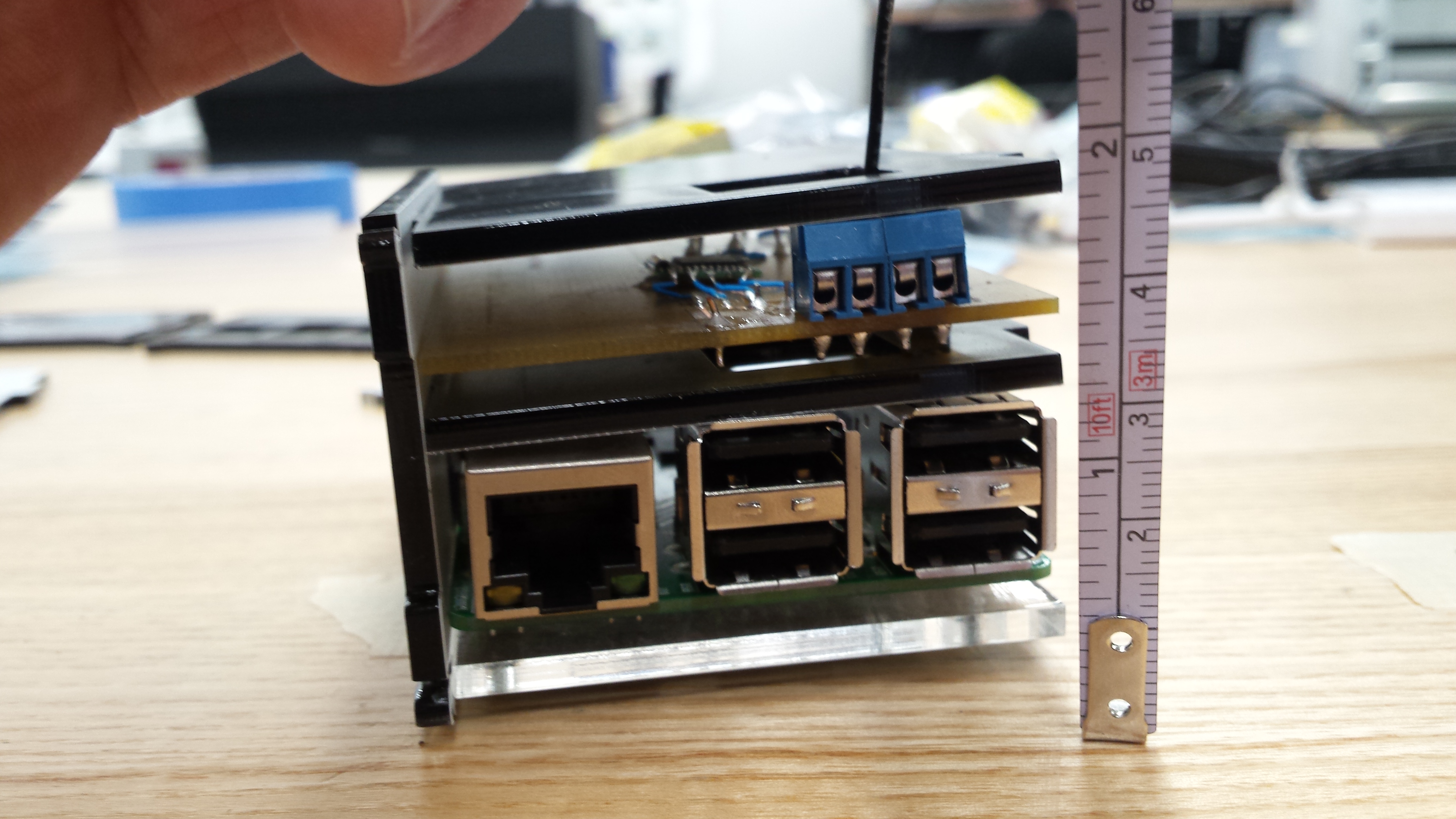
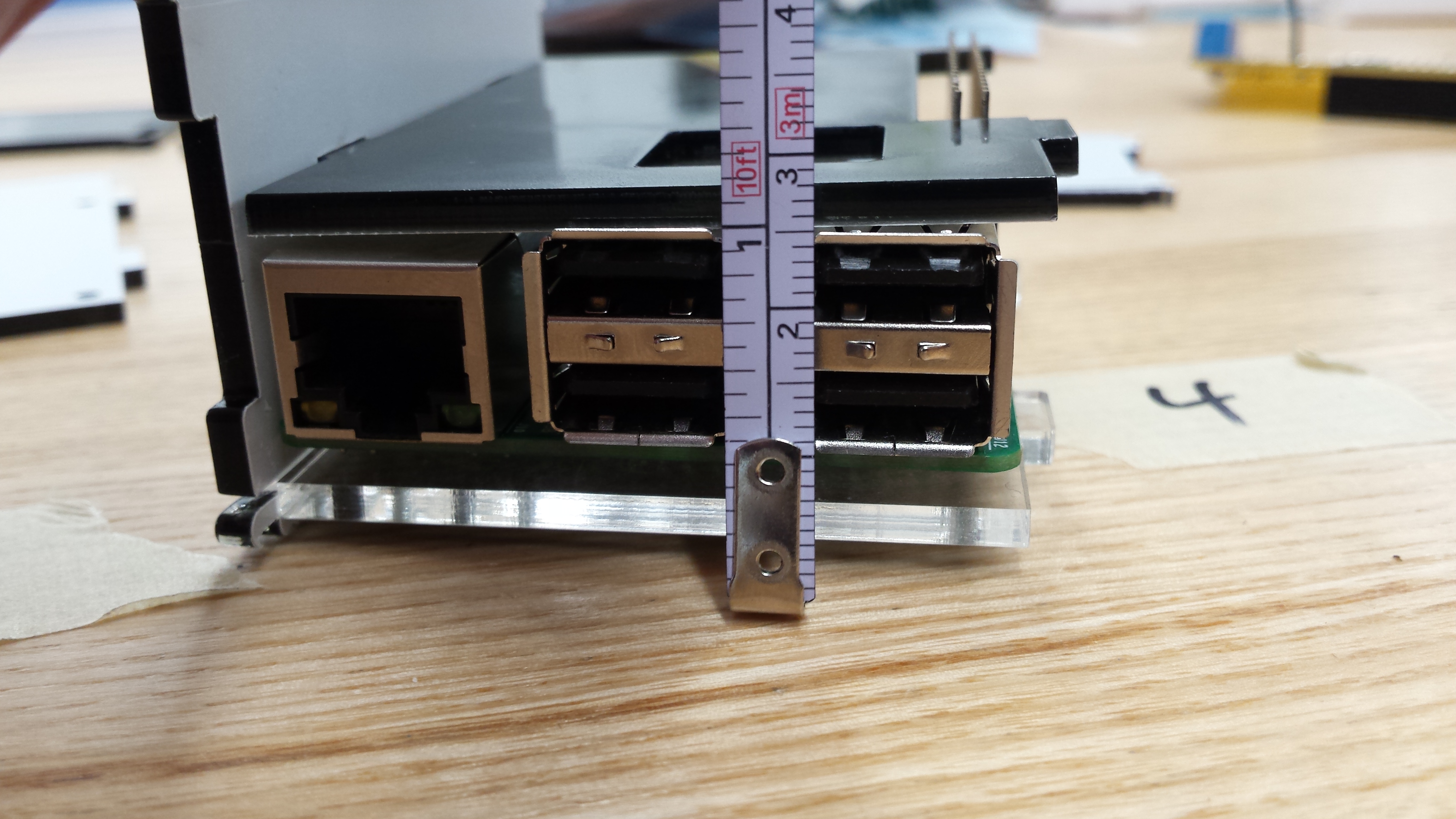
The cutouts for the middle plate are slightly off kilter, as well, the USB ports are pushing up on the plate. My idea here was to support the PCB with the piece of acryillic (with standoffs of course). Tape measure for scale, heres a better picture of my mistake.
I tweaked the drawing in CorelDraw so the cutouts are about 3mm higher for the side plate. The opposite side plate has only one cutout for the on tab on the middle plate. No need to adjust that cutout, however, I had flipped the outline which messed up alignment. Ill need to reprint that side. I had to omit the far end tab to accommodate the 40 pin header. The square cutout (closest to the tape measure) isn't necessary, however, it does make for better passive cooling or some extra space for my soldered pins to float in.
Week 12 (Nov.20th)
My working setup in lab...
Unfortunately, I destroyed my raspberry PI with the newly soldered PCB/device combo. The problem turned out to be my incorrect tracing to ground. When trying to test where the problem originated I ended up connecting 3-5V to the GPIO pin7, frying this board for good.
Luckily, I was able to transfer my SD card with my files and configuration over to a spare PI the parts crib lent me.
So the moral of my story is, double check all your connections before hooking up power, no matter how sure you are.
I began testing my sensor in the lab this week, with some strange results.
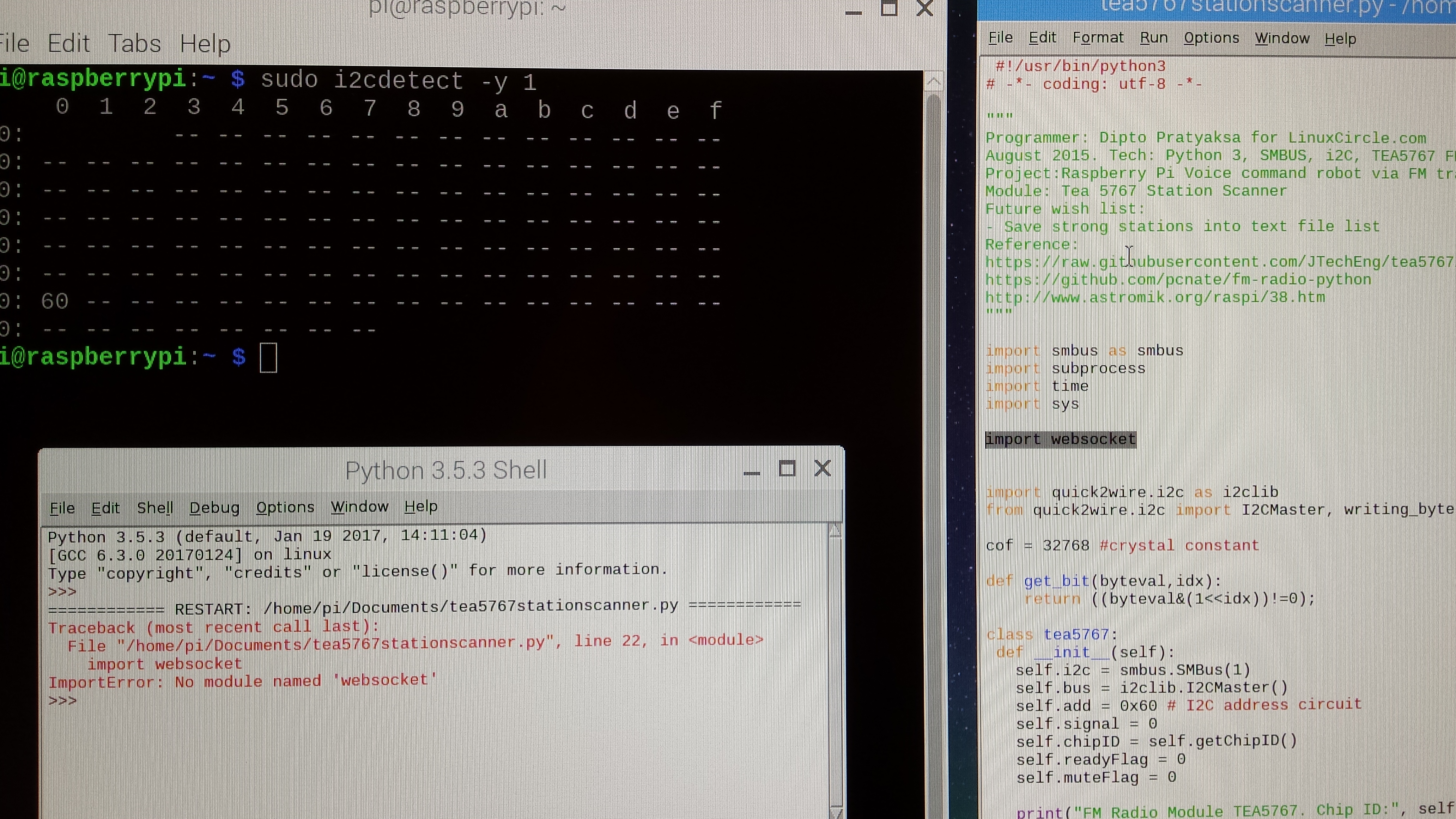
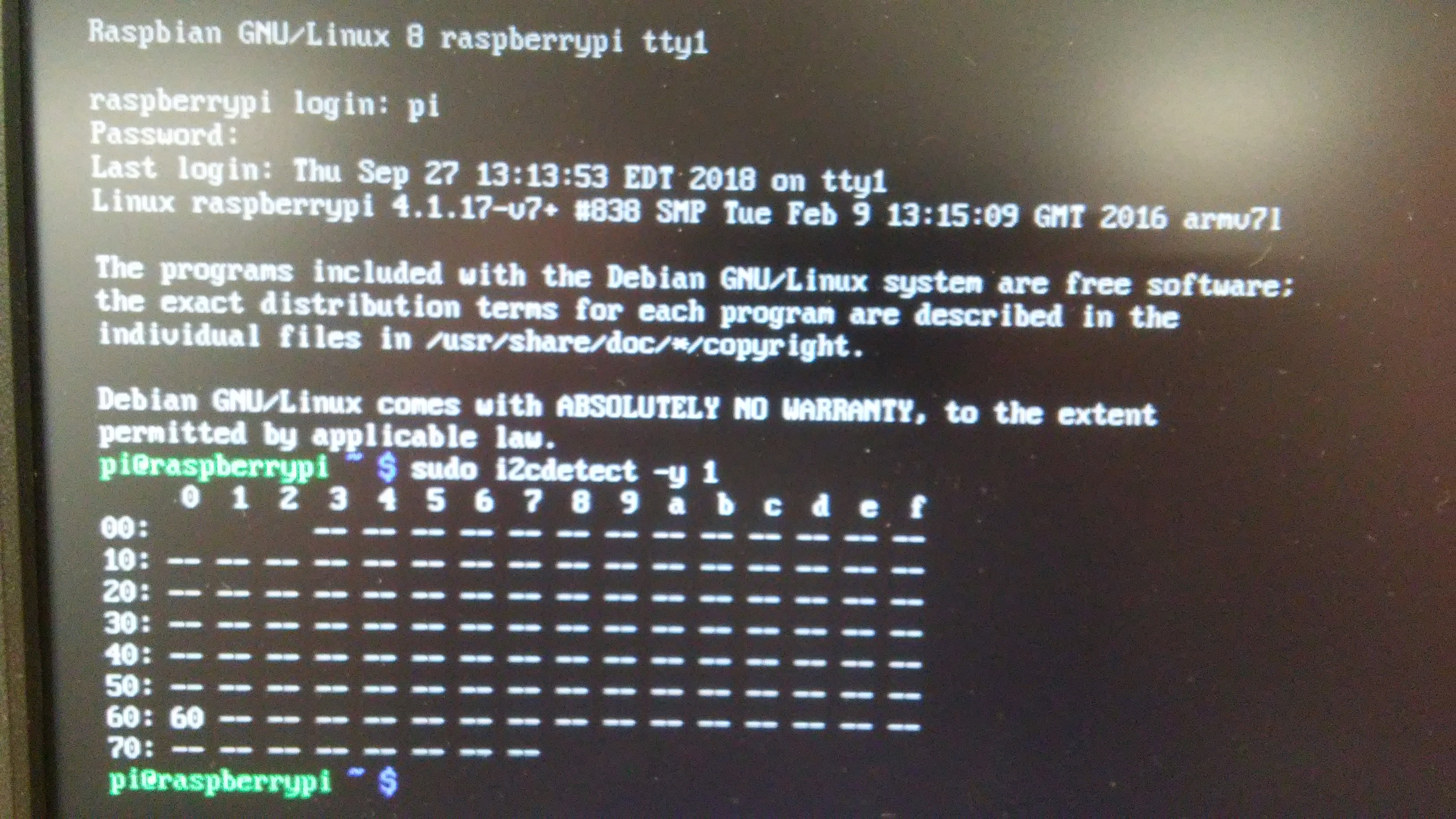
Im able to detect the sensor via i2cdetect (address 0x60) however, when I tried to run TEA5767stationscanner.py the Python shell throws an import error. Ive been trying to resolve this issue with manually updating my python version and its available libraries. With no luck so far. I got the code off LinuxCircle/TEA5767 (on github) which has little info on running the code other than what can be seen here in the comment header. It also lists some further references, which ill be heading to for more instructions and info.
Week 11 (Nov. 13th)
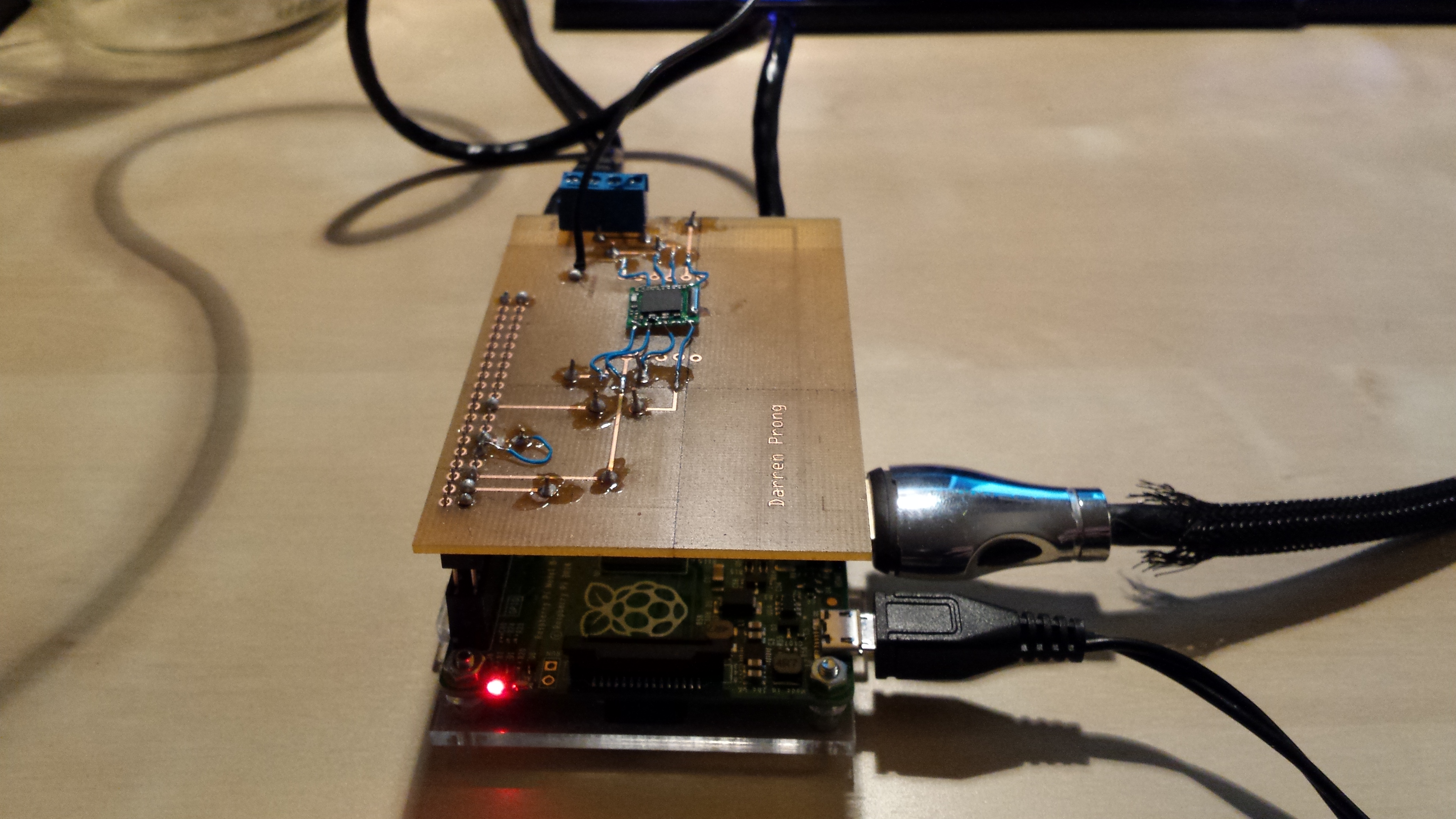
I got most of my parts together and heres them assembled and detected.
im still using the standard case to protect my PI. This case is too small to fit both the PI and the PCB/device, so ill have to modify these files to accomodate both.
Week 10 (Nov. 6th)
Week 9 (Oct.30th)
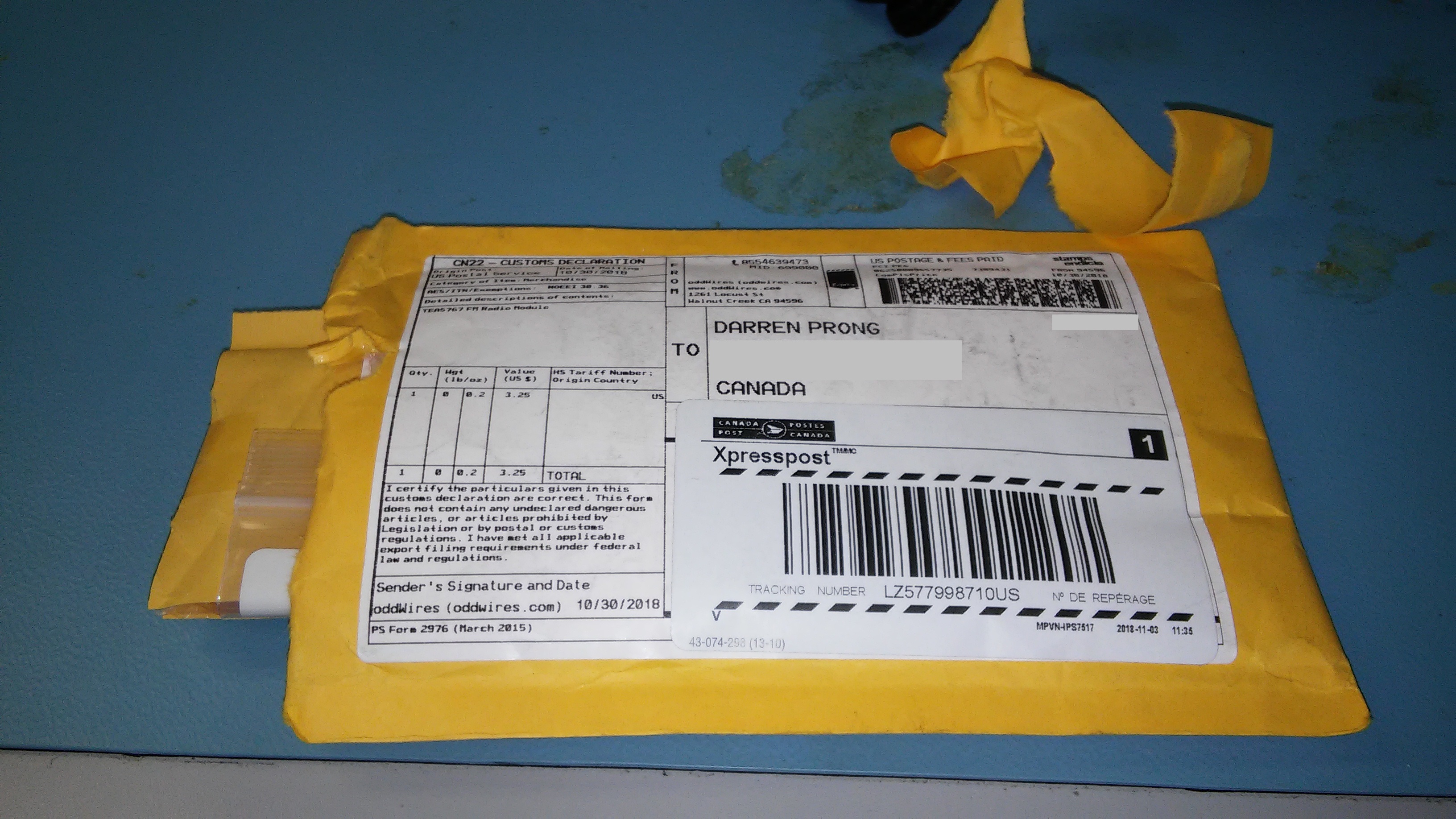
I just received my sensor this week. Would have never arrived if it wasn't for a classmate who had done this class already. He pointed out a great US based website "oddwires.com" which shipped it to me in no time. Next time, don't cheap out on chinese products!
I then asked Vlad in the prototype lab for some help in soldering this onto my PCB. These are the first soldered connections I've ever made.
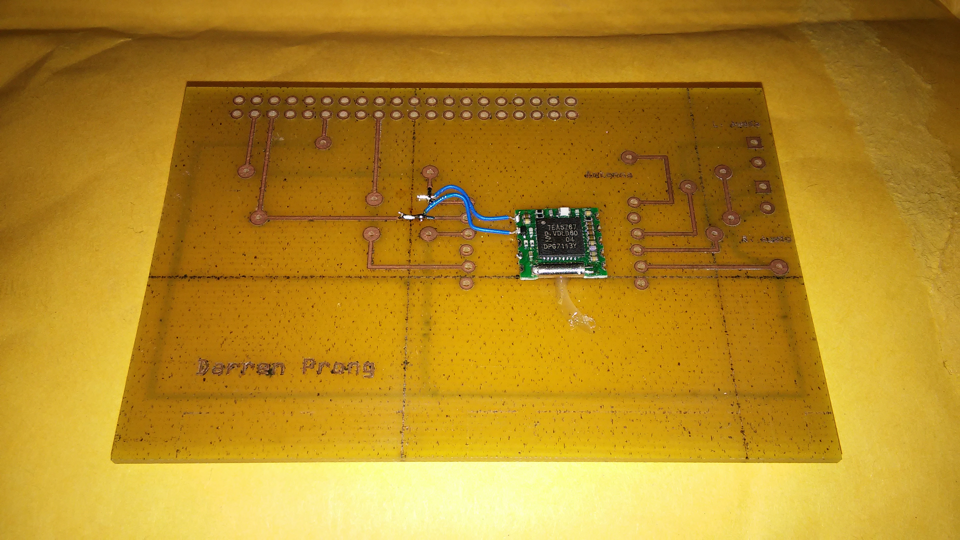
I then moved onto soldering the rest of the jumper wires, and the via's, as well as my two screw terminals for audio Left and audio Right.
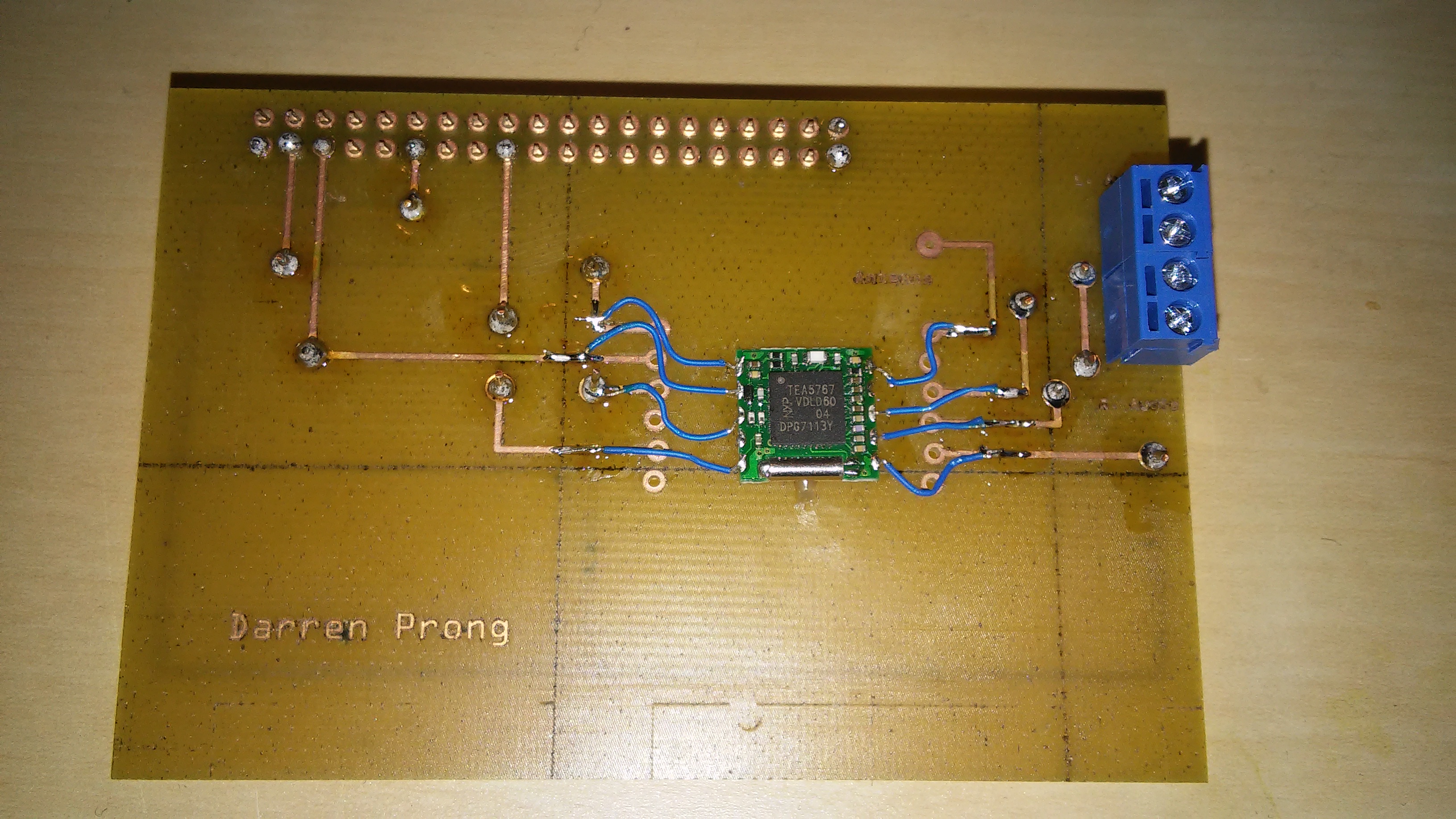
As I had these finished fairly quickly, I measured it up against my PI to see how they would mate-up, and was reminded by a classmate about the stackable headers that were available in the prototype lab. So I grabbed a 40-pin header from the lab and soldered one on.
Unfortunately, the lab had closed up by this point, so ill have to wait till next week to plug it into my PI.
Week 8 (Oct. 23rd)
My sensor has yet to show up, however I decided to prepare my PI before it gets here. My first requirement was to flash an SD card with raspian-stretch (version.x.x), and get it booted up and ready to go.
I ended up with a raspberry PI that couldn't boot, and fear immediately set in that my little computer was Dead on Arrival. All that would display in my monitor was a small lightning bolt in the top right corner beside a "color correction" screen. Kristian (our instructor) informed me that that icon is usually displayed when the PI has recieved insufficent power for the particular power adapter. So we tested a few different power supplies from the parts crib, with no luck unfortunately.
Later that night I messaged the retailer with my issue along with a plea for any additional help. I got a response the next day with a question as to which displays, which power supplies I used and some new info on my particular raspberry PI.
After I responded with the corresponding information, their tech support employee pointed out that the issue could also have been due to an improper flashing of my SD card. I used Win32DiskImager at first, but rushed through the instructions and messed them up obviously. The technician recommended Etcher, I'd never heard of this tool. Its install, and basic UI, and usage made it hard to mess up. Which I didnt, this time.
After I flashed the OS onto the card and plugged it in, the Pi booted up...yay!
So for the first thing to setup was Enterprise wifi. I went onto our course website and downloaded the necessary certificate and copied over the setup instructions into my readme. As with most of these steps, I recieved a lot of help for the two gentlemen in the Prototype lab. Here are some of the instructions I followed:
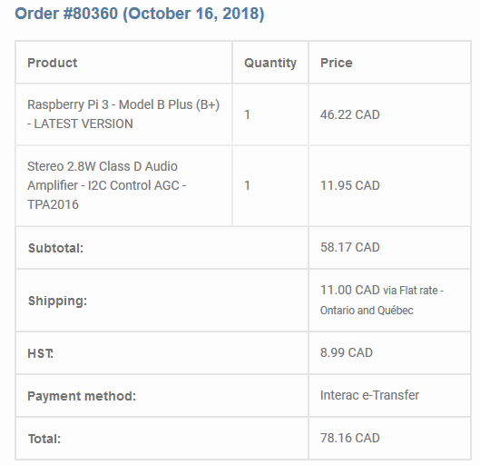
Week 7 (Oct. 16th)
The speakers at the time of ordering werent available; solder turned out not to be needed, I dont need a soundcard, nor a dual channel amplifier. I added them in anyways as it could give me opitons later on down the road if I want to upgrade. I also have a spare set of tweeters floating around my apartment that I could use instead. The PI b+, the Class D amplifier, and the TEA5767 was all purchased on the 16th.
Week 6 (Oct. 9th)
STUDY DAY
On our week off for this class I came into the prototype lab to start designing my PCB; on which my TEA5767 will be mounted. I started messing around with the software, but was also working on finding some other examples online of a completed device. I was hoping to build a more complex version of the device im currently working on, but at the time I realized that a simple FM reciever was the most cost and time-effective way to complete this project. Cost being a significant limiting factor in my situation this semester.
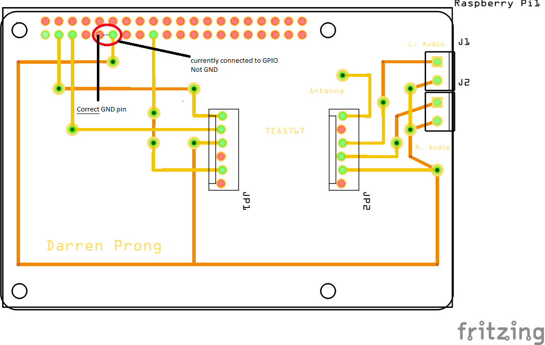
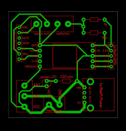
It wasn't until one to one and a half weeks later that I returned to designing my PCB using Fritzing. I'm going to post my progress for that here in order to keep things consistent. I went through a few different iterations of this design, but heres how it ended up being designed:
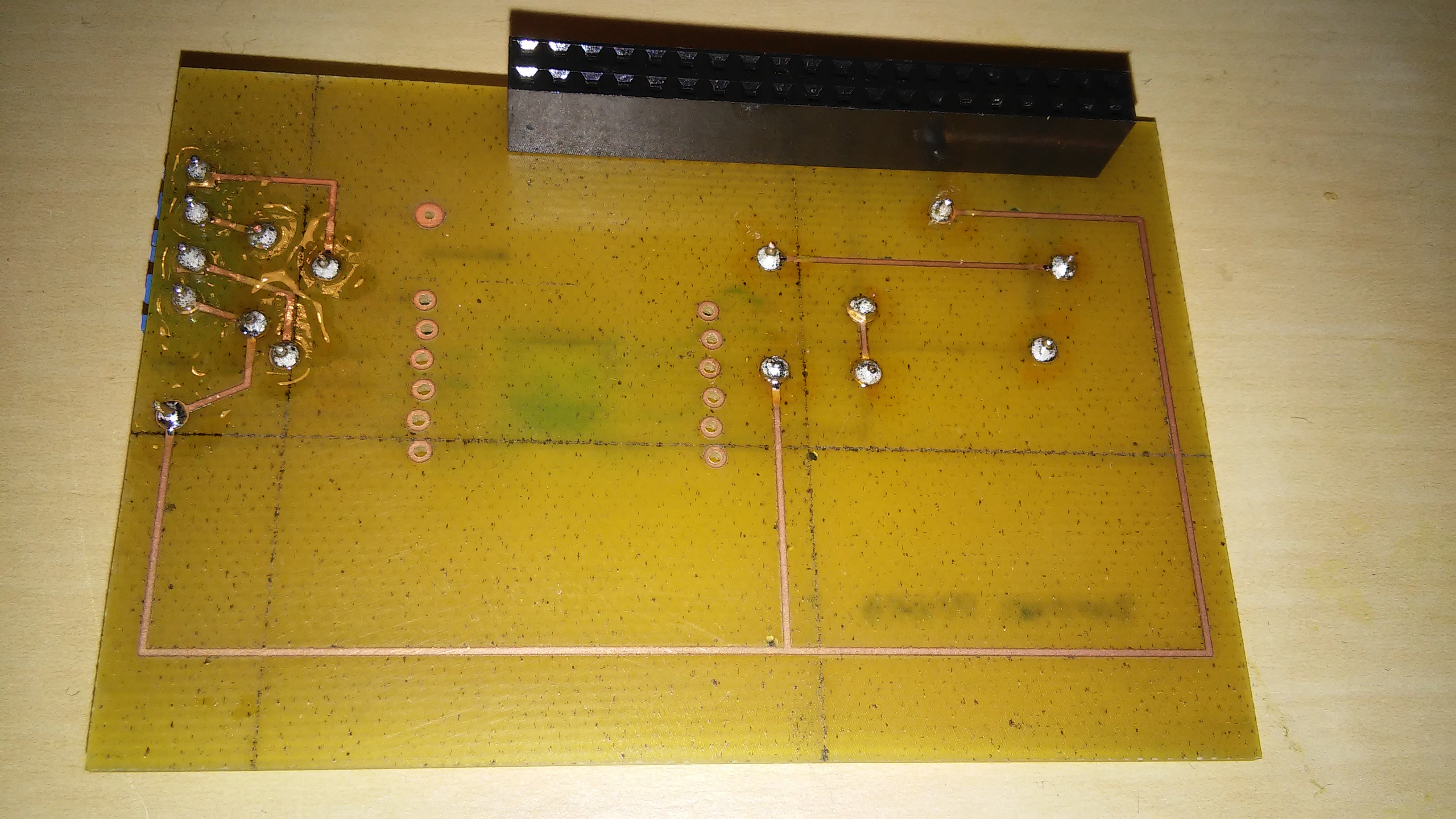
Unfortunately, I made a critical error in this design, which I didnt catch. Even after I had redone this design half a dozen times. My traces to the GND pin in this diagram:
are actually offset by one pin. I wish I had caught this, as when I try to troubleshoot in a few weeks as to why the device isnt being detected, ill short out the PI for good.
Week 5 (Oct. 2nd)
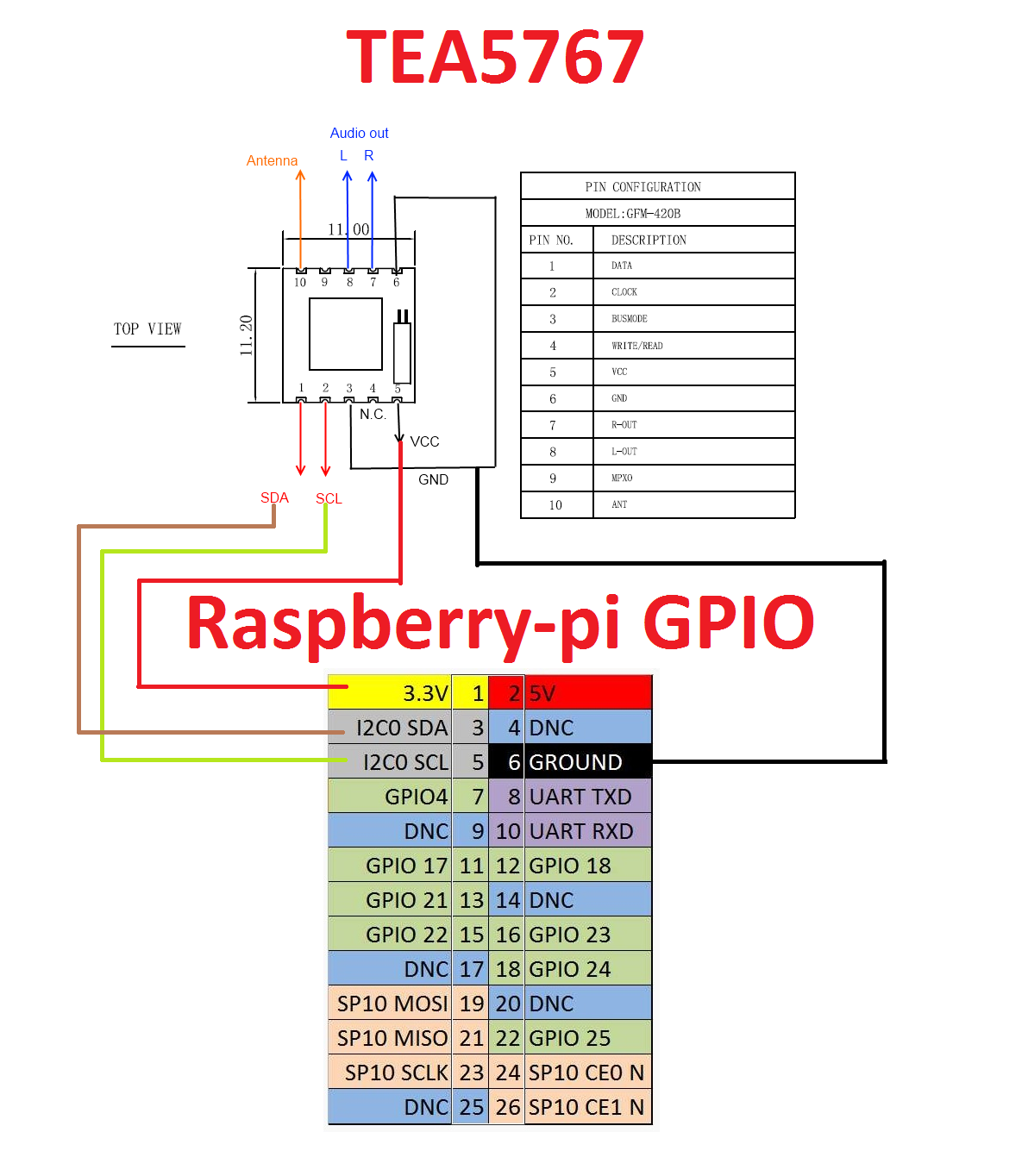
This is a list of pins associated with my sensor
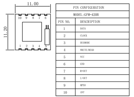
This is how i'll be connecting them to my Raspberry PI
This is an example I found online of the TEA5767 in use. In this particular case, they're using a custom PCB to connect a few different devices to the Raspberry PI. The end goal for this enginneer was to be able to tune, select, play/pause, FM radio stations with an audio amplifier. Routing 2 external speakers to a random amplifier (couldn't find this one online) for audio. A USB hub, to extend the PI's functionality with a Wifi dongle and a Microphone to pick up the voice commands.
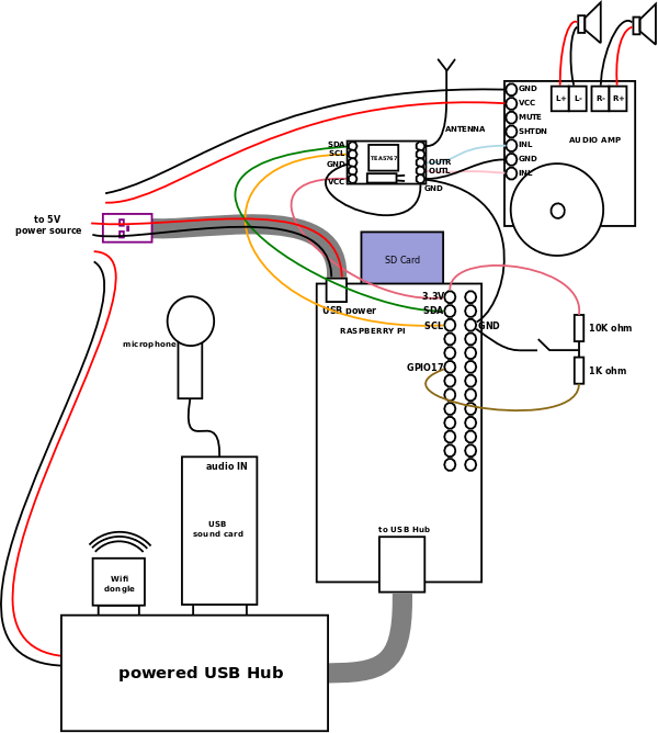
A picture of the prototype they developed:
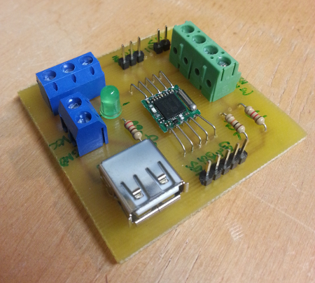
A little too complex for me but the design supplied some good ideas for my own project.
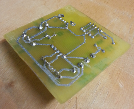
I've never used any fritzing software, but this looks like a good reference to come back to when I start designing mine. They have all the traces on the underside of the PCB. Im not sure if ill have to have them on both sides, it depends on the surface mounts I decide on using.
Week 4 (Sept. 25th)
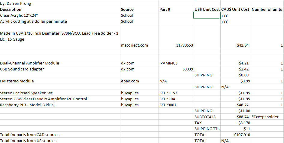
Heres a list of my parts to be ordered: